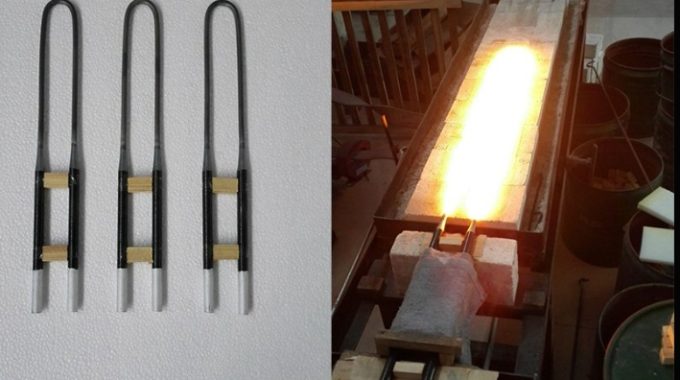

Open-Air Resistive Heating with SiC or MoSi₂ Elements — No Furnace, No Atmosphere Control Both…
How to Calculate Heating Element Power, Quantity, and Size from Furnace Chamber Volume (MoSi2 & SiC)
Designing a high-temperature electric furnace starts with one number you already know: the chamber volume. From that volume you can estimate the total heating power, choose between MoSi2 and SiC elements, set a safe surface load, and then work backwards to the number of elements and the dimensions of each one. This guide walks through the full chain with the formulas furnace builders actually use, plus a complete worked design example. For an instant result, try our heating element selector; this article explains the math behind it.
1. The Calculation Chain at a Glance
- Chamber volume V (liters).
- Total power P = V x q (with correction factors).
- Element type (MoSi2 vs SiC) from temperature and atmosphere.
- Allowable surface load w (W/cm2).
- Single-element power P_elem = w x pi x d x L_h.
- Number of elements N = P_total / P_elem.
- Single-element dimensions (diameter, hot-zone length, cold ends, shank).
2. Step 1 – Estimate Furnace Power from Chamber Volume
Two practical methods give the same ballpark.
Method A – Volume power density. P (kW) = V(L) x q, where q (kW per liter) depends on the maximum operating temperature and element type:
| Max chamber temp | Recommended q (kW/L) | Typical element |
|---|---|---|
| 1200 deg C | 0.30 – 0.40 | Resistance wire / MoSi2 |
| 1400 deg C | 0.45 – 0.55 | SiC (ED) |
| 1500 deg C | 0.60 – 0.70 | SiC / MoSi2 |
| 1600 deg C | 0.70 – 0.90 | MoSi2 (EQ1700/1800) |
| 1700 deg C+ | 0.90 – 1.20 | MoSi2 (EQ1800/1850) |
Method B – Empirical V^(2/3). P (kW) = K x V_m3^(2/3). Typical K values: 650 deg C -> 35-50; 850 deg C -> 50-75; 1000 deg C -> 75-100; 1200 deg C -> 100-150; extend to 1600 deg C as a planning value of roughly 200-300.
Correction factors (multiply P): temperature margin near the element limit +10-20%; shape (rectangular/box 1.2-1.3, cylindrical 1.1-1.2, slender 1.3-1.5); duty (continuous 1.0, intermittent 1.1-1.2, frequent door opening 1.2-1.3); fast heat-up 8-10 deg C/min +15-20%. Note that specific power falls as volume grows (P/V is proportional to V^(-1/3)), so large furnaces need less per liter than small ones.
3. Step 2 – Choose MoSi2 or SiC
| Max temp | Atmosphere | Recommended element |
|---|---|---|
| up to 1400 deg C | Air / oxidising | SiC (ED grade) – cost-effective |
| 1400 – 1650 deg C | Air | MoSi2 EQ1700 |
| 1650 – 1800 deg C | Air | MoSi2 EQ1800 / EQ1850 |
| N2 | SiC to ~1370 deg C, MoSi2 to ~1600 deg C (derate) | |
| Hard vacuum | Not recommended for either (SiO2 layer cannot regenerate) |
See the full MoSi2 guide and SiC guide for grades, diameters, and selection rules.
4. Step 3 – Allowable Surface Load (W/cm2)
The surface load is the single biggest factor in element life. Stay below the planning maxima and derate for corrosive or reducing atmospheres.
| Element temp | MoSi2 (air) | SiC (air, design) |
|---|---|---|
| 1200 deg C | ~14 | 9 – 11 |
| 1400 deg C | ~16 | 3 – 4 |
| 1500 deg C | 14 | (near limit) |
| 1600 deg C | 12 | – |
| 1700 deg C | 8 – 10 | – |
| 1800 deg C | 6 | – |
Rule of thumb: lower load equals longer life – when in doubt, go one size up.
5. Step 4 – Power per Single Element
P_elem (W) = w x A_h, where A_h (cm2) = pi x d x L_h, d = hot-zone diameter (cm), L_h = hot-zone length (cm).
MoSi2 example: Phi 6/12, L_h = 200 mm = 20 cm. A_h = pi x 0.6 x 20 = 37.7 cm2. At 1600 deg C, w = 12 W/cm2 -> P_elem is about 452 W.
SiC example: phi 20 mm x 400 mm (d = 2 cm, L_h = 40 cm). A_h = pi x 2 x 40 = 251.2 cm2. At 1200 deg C, w = 10 W/cm2 -> P_elem is about 2512 W.
6. Step 5 – Number of Elements
N = P_total / P_elem, rounded up. Group N so it divides evenly across chamber walls and electrical phases or zones (for example 3-phase loops in multiples of 3, or series/parallel groups of 2). Keep one or two spare elements on hand. Distribute elements on the side walls, top or bottom, and the back; avoid crowding near the door. In the MoSi2 example above, a 20 kW furnace at 452 W per element needs about 44 elements – choose 45 and group as 3 zones of 15.
7. Step 6 – Single-Element Dimensions
- Diameter pairs (hot/cold, mm): Phi 3/6, 4/9, 6/12, 9/18, 12/24.
- Hot-zone length L_h: set by the furnace dimension the element spans (chamber height or width) minus about 20-30 mm wall clearance.
- Cold-end length: typically 200-400 mm to clear the insulation and reach the terminals.
- Shank (leg) spacing for U-type: match wall thickness and terminal layout (common 50-80 mm).
- Overall U-type length is roughly 2 x cold-end + hot-zone.
Thinner elements (Phi 3/6, 4/9) give more elements and better temperature uniformity; thicker elements (Phi 9/18, 12/24) give fewer elements with higher per-element power.
8. Full Worked Design Example
Given: box furnace, chamber 250 x 250 x 400 mm (W x H x D), maximum 1600 deg C, MoSi2 EQ1800, air.
- Volume: V = 25 x 25 x 40 / 1000 = 25 L.
- Power: P = 25 L x 0.8 kW/L = 20 kW (upper end of the 1600 deg C band for fast heat-up). Check with V^(2/3): V_m3 = 0.025, V^(2/3) = 0.085; K is about 235 -> P is about 20 kW. Consistent.
- Element: MoSi2 EQ1800, hot/cold Phi 6/12 mm.
- Hot-zone length: span chamber height 250 mm, leave 25 mm clearance top and bottom -> L_h = 200 mm (20 cm).
- Surface area: A_h = pi x 0.6 x 20 = 37.7 cm2.
- Allowable load at 1600 deg C: 12 W/cm2.
- Single-element power: P_elem = 37.7 x 12 = 452 W.
- Number: N = 20000 / 452 = 44.2 -> 45 elements.
- Arrangement: 3 zones x 15; for example left wall 12, right wall 12, back 10, top 11 (door side left open), then grouped into phases.
- Dimensions per element: hot zone Phi 6 x 200 mm; cold ends Phi 12 x 250 mm each; shank spacing 60 mm; overall length about 250 + 200 + 250 = 700 mm.
Result: a 20 kW MoSi2 furnace built from 45 x Phi 6/12 U-type elements with a 200 mm hot zone.
9. Frequently Asked Questions
How do I estimate furnace power from chamber volume?
Use the volume power-density method: P (kW) = V(L) x q, where q is about 0.30-0.40 kW/L at 1200 deg C, 0.45-0.60 kW/L for SiC service near 1400 deg C, and 0.80-1.20 kW/L for MoSi2 service at 1600-1700 deg C. Multiply by correction factors for shape, duty cycle, and heating rate.
Should I use MoSi2 or SiC heating elements?
Choose by maximum chamber temperature and atmosphere. SiC (ED grade) is cost-effective up to about 1400 deg C; MoSi2 (EQ1700/EQ1800/EQ1850) is required from 1400 deg C up to 1850 deg C. Neither is recommended for hard vacuum because the protective SiO2 layer cannot re-form.
What surface load should I design to?
Surface load (W/cm2) is the main life limiter. Planning maxima: MoSi2 about 12 W/cm2 at 1600 deg C, 8-10 at 1700 deg C, 6 at 1800 deg C; SiC about 9-11 W/cm2 at 1200 deg C and 3-4 at 1400 deg C. Always design with margin and derate for corrosive or reducing atmospheres.
How many heating elements do I need?
First compute single-element power P_elem = w x pi x d x L_h, where w is the allowed surface load, d the hot-zone diameter, and L_h the hot-zone length. Then N = P_total / P_elem, rounded up. Arrange N so it divides evenly across chamber walls and electrical groups (phases or zones).
How do I size a single heating element?
Pick the hot-zone diameter from standard pairs (Phi 3/6, 4/9, 6/12, 9/18, 12/24 mm), set the hot-zone length to span the furnace width or height with about 20-30 mm wall clearance, then choose cold-end length (usually 200-400 mm) and shank spacing to match wall thickness. Overall U-type length is roughly 2 x cold-end + hot-zone.
10. Why Specify Heating Elements With HeatingDriver
HeatingDriver is a manufacturer and exporter of MoSi2 and SiC heating elements with nearly 20 years of experience supplying furnace builders, labs, and integrators worldwide. We stock standard grades and build custom sizes from your drawings, and we review your element drawings free of charge before production. Use our heating element selector for a quick power and quantity estimate, browse the full specification library, or read the complete guides to MoSi2 and SiC elements. For furnace context, see our guides on the muffle furnace, tube furnace, vacuum atmosphere furnace, and chamber furnace.
Related Posts